I can’t comment on those specific cables as I was lucky to get some that came with my board. I did order some longer additional cables from a different seller and sadly those didn’t work at all.
Was this the same seller or a different one? Can you post pictures of this board? I’m curious of the differences.
Unless they (Stern) made a change for the European market, I believe they are 768.
We tried getting this going for the NWPC but I ran out of time to fully test. How loud is the sound level?
Maybe. I’m worried about damaging my pin though. Sounds like from @GeekGamerTV that it may be a cable issue. Or maybe they have changed the board design.
I’ve ordered the parts and studied this thread and other resources. If I can make this work, I’ll do a video outlining the exact process. The biggest pain is sourcing all the parts. If I can get it to work, I’ll make some extra setups for others.
It seems to me with the LVDS-HDMI board, there are “multiple models” but really there isn’t. There’s one model, and there’s a jumper you have to add to enable/disable single/double mode - apparently by default it’s enabled for 1080 but need this jumper to make it work with lower resolutions? that’s my understanding at this point. I also assume the second connector is a pass-thru? So a splitter board isn’t needed? Can anybody confirm that? I should have the parts in a few days to try myself.
My board will be here by Friday and I’m keeping my fingers crossed that it will work. I’ll be testing on my Stern Star Wars.
My understanding is that when you order the board, you need to specify the single 8 version and it will come ready for 720p/768p/960p. If not, it comes ready for 1080p. You can modify the board to change it from double to single if you didn’t specify. It sounds like one of the issues now is that the board used to come with a cable and now it doesn’t, so you have to order one and that may be a source of the problems some people are having.
Confirmed (at least with my capture board) that it passed the signal. Was prepared and used the splitter board at first, but noticed that per the pinout it should pass through the signal and sure enough it did! It helped cut down on the amount of items needed.
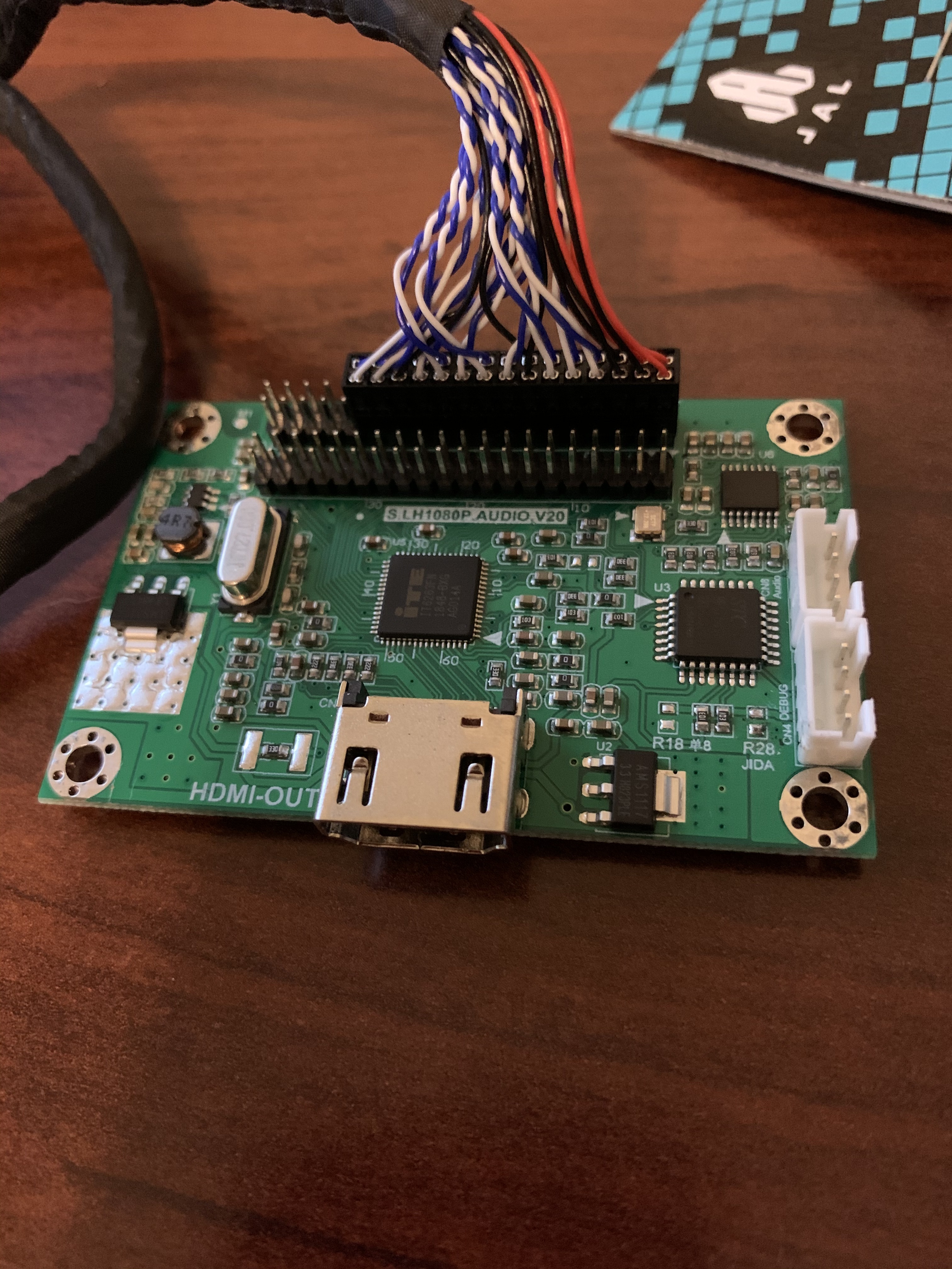
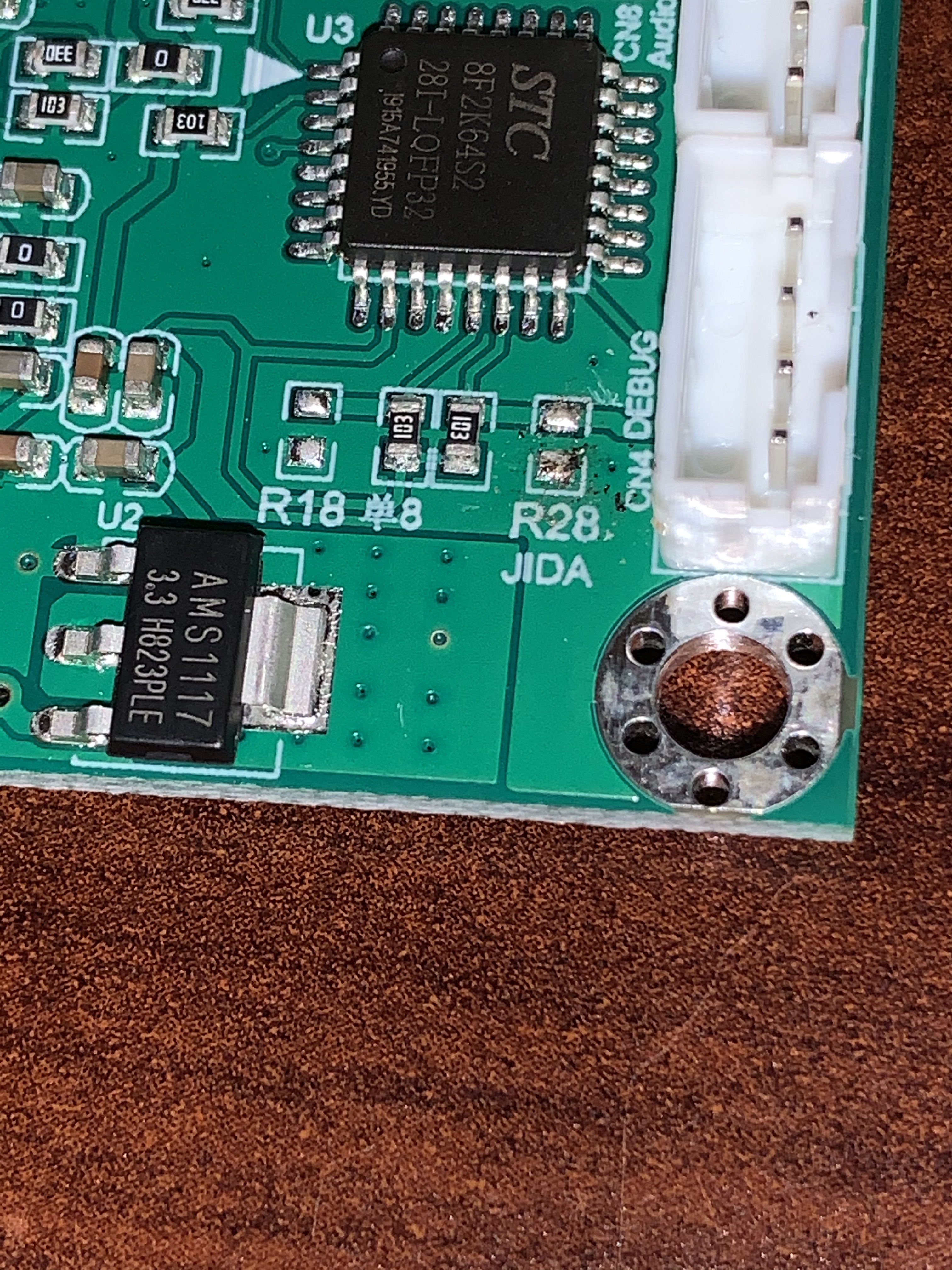
I got no passthrough, and no video. I did note just now that R28 (which is supposed to have a 0 ohm resistor “welded” to it) has fallen off. So maybe restoring that will get it working, but I am spooked. Is yours like this with the 2 white connectors on the side?
I still have some question about how it attaches to the Stern motherboard. I plugged it in right justified - no empty pins - but if the original Stern connector had blanks there, should it be shifted over one to the left? I am confused and not wanting to take a chance that fries the board.
Does the small capture board require the hdmi to be hooked up to power the passive splitter? I hooked everything up without the hdmi plugged in and I just got a white screen on the LVDS display.
Sounds like you might have the pins not correct Patrick. Stern one is one over and then on the other cable pin1 needs to match pin 1 - make sure you power off though!
Anyone who bought the 30p extension cable from Aliexpress above, that will not work. However, you can make it work with a pin (the sewing kind) and some patience. You need to go through and swap each pair of wires, vertically on one side.
I did this and got passthrough working. I have not got my laptop to recognize it yet through my HD60S. It is showing it has a signal at the correct resolution, but I have not got it to work yet.
Depending on what LVDS cable you get, it may be the wrong “handedness”, and you may have to test your patience and re-pin the cable The cables you want will generally have a red dot on the connectors, as opposed to a white dot.
On an LVDS cable, there will be a corner of 3 red wires. The corner red wire is pin 1, probably marked by a dot on the connector. On the LVDS board, pin 1 is marked by a triangle. On the Spike display cable, this should match with the pink wire.
For connecting the Spike CPU board to the converter, you’ll have to move a standard LVDS cable one pin to the left on the Spike CPU board side, so the far right pins are open (notice how they’re open on the Spike display cable connector).
From the converter board passthru to the Spike LCD display, you’d have to move the cable one pin to the right on the converter board side. Visually inspect and make sure the pink wire matches up with pin 1. The connector will be hanging off the edge of the pins.
@GeekGamerTV’s pic and videos show how you have to shift the cables by one pin.

 The cables you want will generally have a red dot on the connectors, as opposed to a white dot.
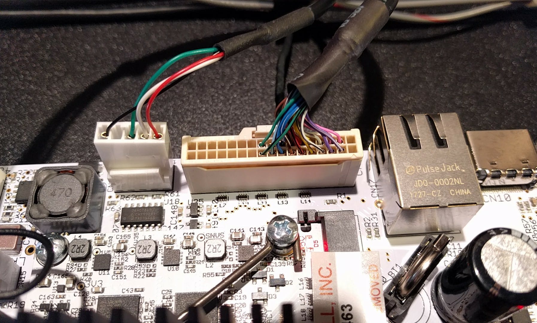