Yesterday I tried plugging into the HDMI port on the CPU board in an Aerosmith Pro. This port controls the mini-screen on Batman 66 and SW but is unused on AS.
Unfortunately, it doesn’t seem to output anything. Maybe it would only need a software tweak to mirror the main display?
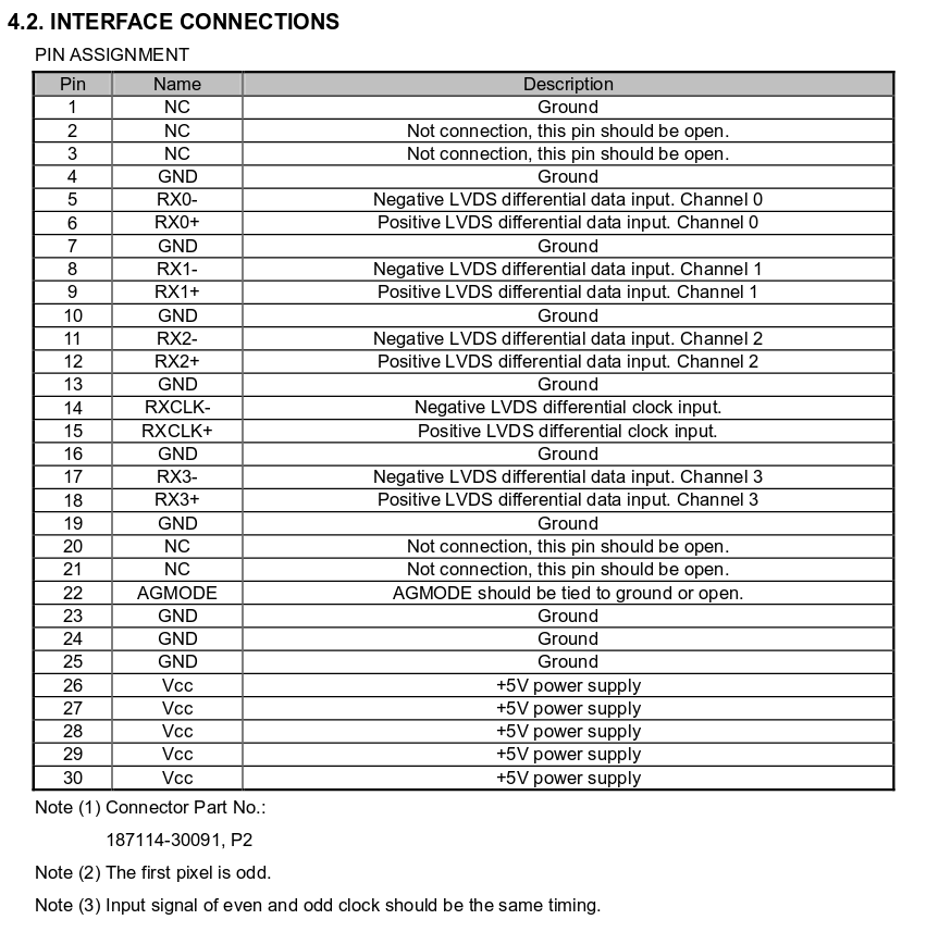
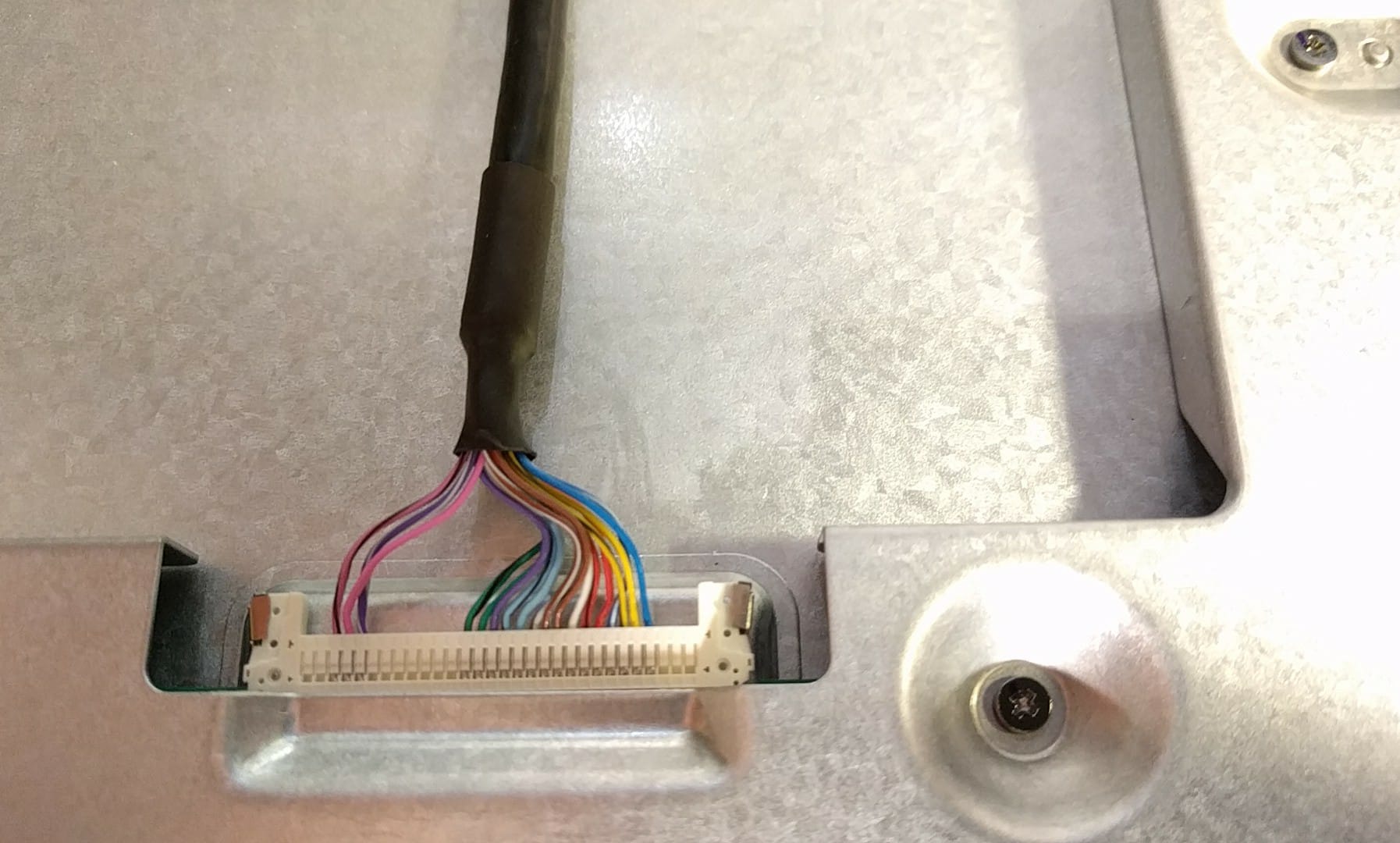
bump… got a tournament coming up that might need this. I have some ideas on solutions, and a pile of LVDS/TTL crap in a box somewhere in my house. Can someone pop a photo of the connector on the LCD? Not on the Spike 2 board itself, but on the LCD.
No connector photos as I don’t have a game myself, but possibly useful is that I scribbled down “Innolux G156BGE-L01” in that thoughts file. Fairly sure that’s the reference part, if you wanted to check out the datasheet.
another edit:
After a little googling, I think the “,P2” in that connector part number actually refers to the part manufacturer “P-TWO”. Here’s the panelook page listing (among other things) matched/compatible parts.
Been making slow progress, unfortunately I don’t own a Spike 2 machine of my own so my time to actually work on this and test is limited. I’ll share what I’ve done so far in case others have advice!
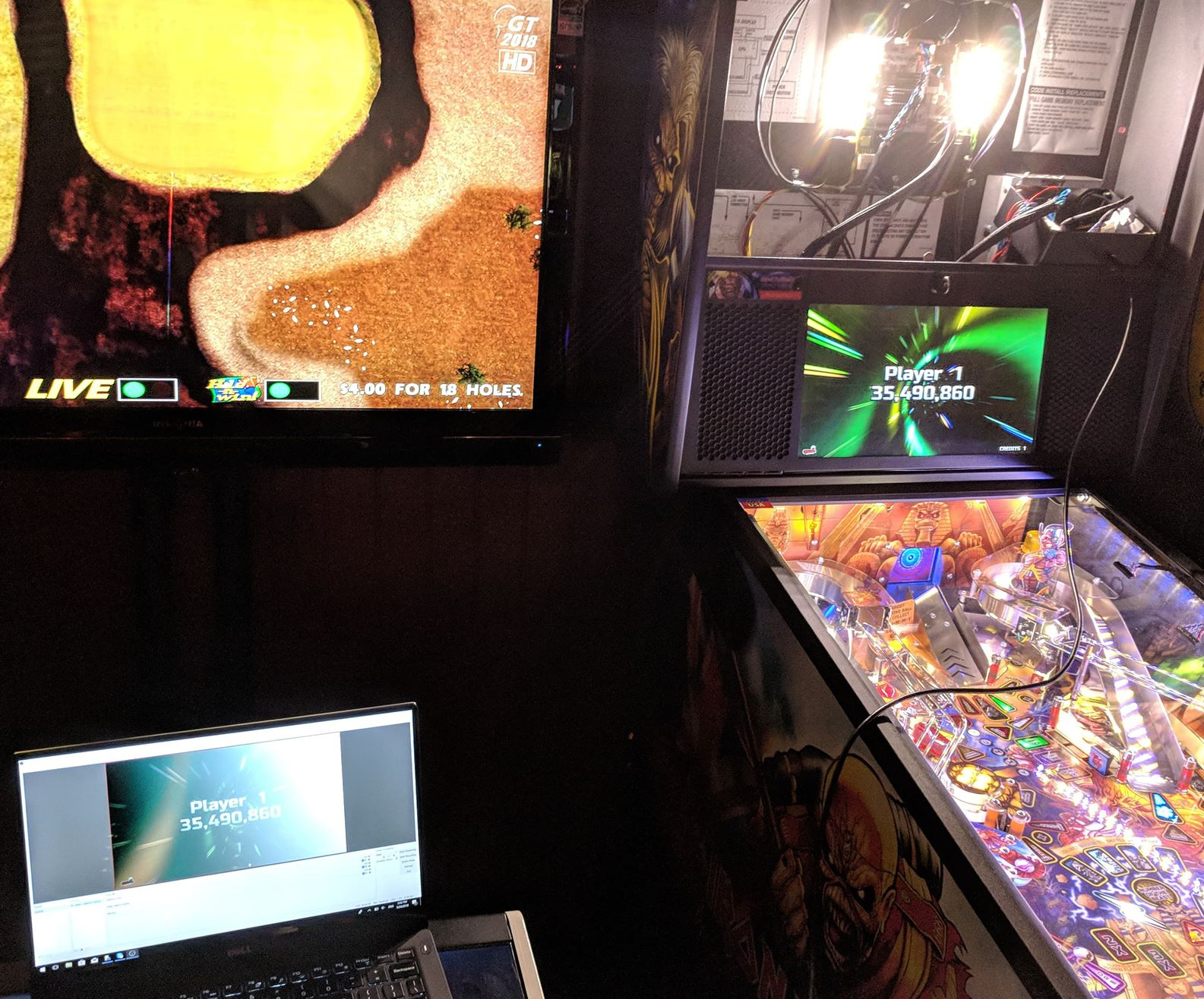
Edit 06-29-2018: Got this all working successfully. It specifically requires the single channel version of the LVDS-to-HDMI converter to convert the 1366x768 resolution of the Spike 2 display.
(The following was my original post, but now everything is working correctly with the single channel version of the LVDS-to-HDMI converter.)
I’m successfully splitting the LVDS signal, so I still get a perfect display on the pinball’s LCD. But I haven’t been able to successfully capture the HDMI output yet. The resolution of the screen is 1366x768, but my elgato HD60S in OBS will only let me specify 1360x768, which results in white stripes on the screen due to the resolution mismatch. Also, the signal seems to cut in and out, but maybe this problem will vanish when I am able to capture the correct resolution. I might try to get an HDMI upscaler and see if that solves this issue.
Thanks for the pinouts @jrb , they were very helpful. They match the pins on the LCD connector. On the Spike 2 board, it’s a 2-row connector with the pins shifted one to the left, i.e. Pins 3 and 4 are the +5v that connects to Pins 1 and 2 on the LVDS splitter.
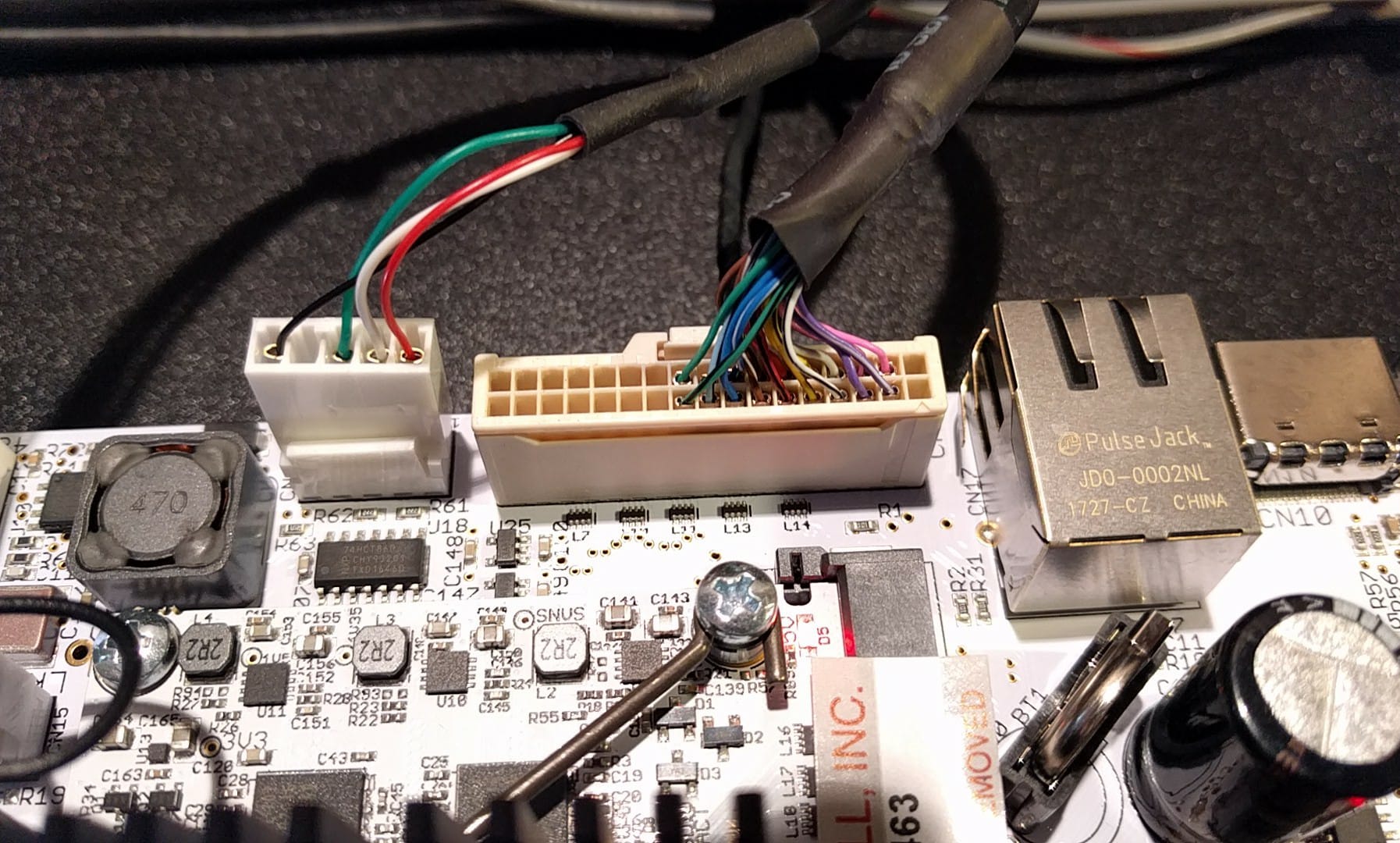
The 34-pin Molex connector used on the Spike board does not mate nicely with the usual LVDS dupont connectors – they are different crimps, so the LVDS cables wouldn’t hold in place. I found the specific Molex connector and made some of my own LVDS cables using some wire and a lot of patience. This also let me offset the pins to the left so that they match the spike board. I have a cable running from the Spike board to the splitter input, a cable running from the first splitter output to the LCD, and a cable from the second LVDS output to the HDMI converter.
The LVDS splitter is powered by 5v from a JST connector. I just soldered the 1st +5v pin of the LVDS connector to this power pin. As a bonus, the HDMI converter can also take audio in from a JST connector, so I think you could connect an 3.5mm phone jack to this board and get game audio over HDMI.
Here are pics of the Spike connectors as requested above:
Nice progress! Pretty straightforward overall, as long as the correct cables could be sourced.
the cutting in and out sounds like it would be a power issue rather than a resolution issue but that’s just a guess. Is the LVDS to HDMI powered by the LVDS cable? I wonder if an external 5V power (for both boards) might be worth trying before buying an upscaler.
Regarding audio over HDMI, does Spike 2 have a 3.5mm audio out on the board?
Sorry I may have been mistaken on spike 1 there is 3.5mm audio on spike 2 there is a connector that you can use to grab the audio with a suitable cable that would be simple to make up - I’ll try and find the diagram for it.